Saturday, March 21, 2015

Equalizer design and Analog Dial Implementation


Design for a vintage styled equalizer interface. Graphics were created for dials and switches: metal slider, animated screw-heads, and back panel inspired by old radio equipment.

It can be considered a test version. Be careful when processing audio with it. There are limiters in place to prohibit peaks, but they can be removed by turning either of the lower brass inlets. now you are free to overload the unit, yet, do so at your own risk. If necessary, one can screw around with the frequency centers using a flat head driver. channel potential is 10-16000hz.

Install the plugin by placing the file into a folder which your vst host will recognize as a plugin repository.

Download VST Plugin

color controls

color wheel control and palette manager. These interface controls for selecting colors, were built as an exercise. It consists of a radial hue selector, saturation and lightness xy pad, and small preview swatch. next a swatch array was added to store color settings. clicking any area in the grid will select a color slot and can output the stored color.
DOWNLOAD CONTROL DEMO


color wheel module diagram


The main colorwheel consists of 5 modules applied to the view in sequence. "Drag angle" determines the radial direction of user mouse drag. converting an x,y ray extending from the center to 360 degree outward. this range determines the hue.

calculating ray angle


inside 'radial 360' module: fixes angle direction sector and offsets


"center blend" is an xy accumulator with range conversion between 0-255 on each dimension. the display for the center square is pair of layered gradients of value and saturation. the input hue is shifted based on current rotary degree selection.
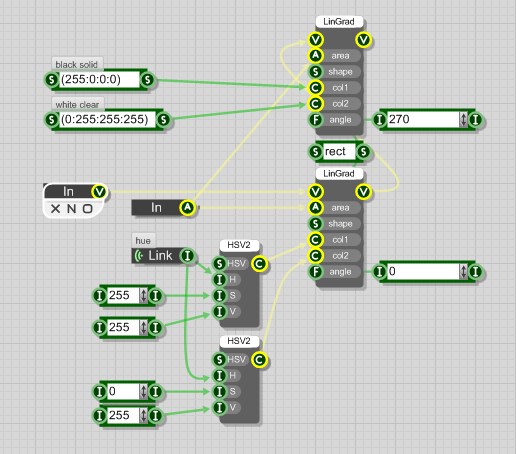
center blend for sat-val display


The swatch array is built upon modules with multiple index synchronized arrays.
inside main schematic block


the columns are created by a little module that reads the index elements, calculates the space available in the view box, and fits as many into rows and columns as possible within size and margin dimension constraints.
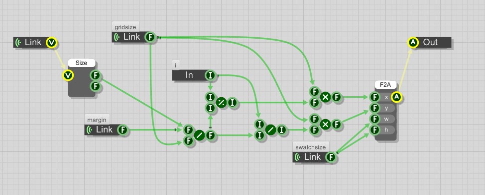
columnizer: take note of integer to float conversions


there is also a module that kind of reverses the process. it converts mouse x,y click to grid units, and finds out what array index that mouse click is contained within. then the columnize module puts the highlight rectangle around that box.
find index by x,y


swatch array: each trigger activates both


The basis is the 'color array', which consists of 4 arrays, one for each A,R,G,B value. they are added and retrieved at once by index, and can get and set values with triggers. below is the color array 'edit' module, which is paired with a duplicate color array 'read' module. they are synchronized to solve a problem with modifying colors while the draw loop is setting the index value.
color array edit: access to color array items happens here.


Signal Generator interface design

The concept for this project was to be a signal generator, inspired by hardware oscilloscope. This device is used for testing sound output and frequency response in speakers or microphones. Control parameters were defined and assembled into a front panel, graphical elements illustrated as bitmap.

DOWNLOAD DEMONSTRATION VERSION
Download VST Version

Disclaimer:
Consider this a test unit, it may not work entirely as expected, and will be improved and updated as i learn.
Take care in its operation, as it can produce a wide range of signals; some settings could produce sounds with the potential to cause damage to your ears, and sound equipment. explore at reasonable levels. you will assume the risk.


functions include:
power (on/off): volume control, decibel level meter
modes: noise, sine, sweep
signal filtering: lowpass / highpass (with on/off)
oscillator module (on/off): dual oscillators with independent multiplier
channel shifting: 
 (a/b faders): channel delay, L/R shift
 (switches): delay invert and fade type(crossfade or blend)
main display: switchable(waveform/spectrum), sweep rate, frequency control, image hold.

Operation Overview:
Before switching power on, ensure the large volume dial is set at its lowest value (S/W direction) by clicking  and dragging down while over its image. tap the switch labeled "power"; a green light will confirm generator activity. slowly rotate the volume dial by vertical drag. choose an emitter type with the small silver dial below output volume. this can select either noise, tone, or sweep. following to the right of this selector, 2 small inset dials on the display, control sweep velocity and tone frequency. above them, the monitor shows their current values. also nearby, it shows decibel value. a switch at the top right of the display can flip between waveform or frequency graph projection (still in need of adjustment). at the lower right of the unit, two black faders have an effect on channel offset. the top can delay a channel up to 500 samples. the lower shifts left or right dominance. when the light below illuminates, center position is absolute. there are some tiny little switches on either side. the first indicates which side is being delayed. the other determines whether the sliders fade or blend across channels. very slight differences, mainly experimental. filters can be activated with the switch between filter dials. on the left increase lowpass filter to cut off high frequencies. on the right, highpass can exclude low frequencies. the oscillator module next door will modulate a tone at a wide range of speeds. the switch give can access to even higher rates. there happens to be a co-oscillator, to add further disruption. sometimes a complex or unpredictable tone can be created.